

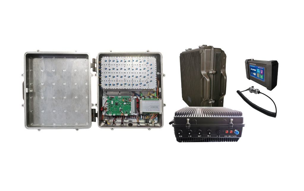
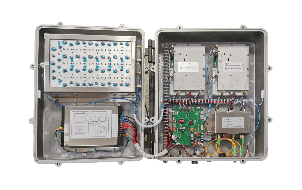
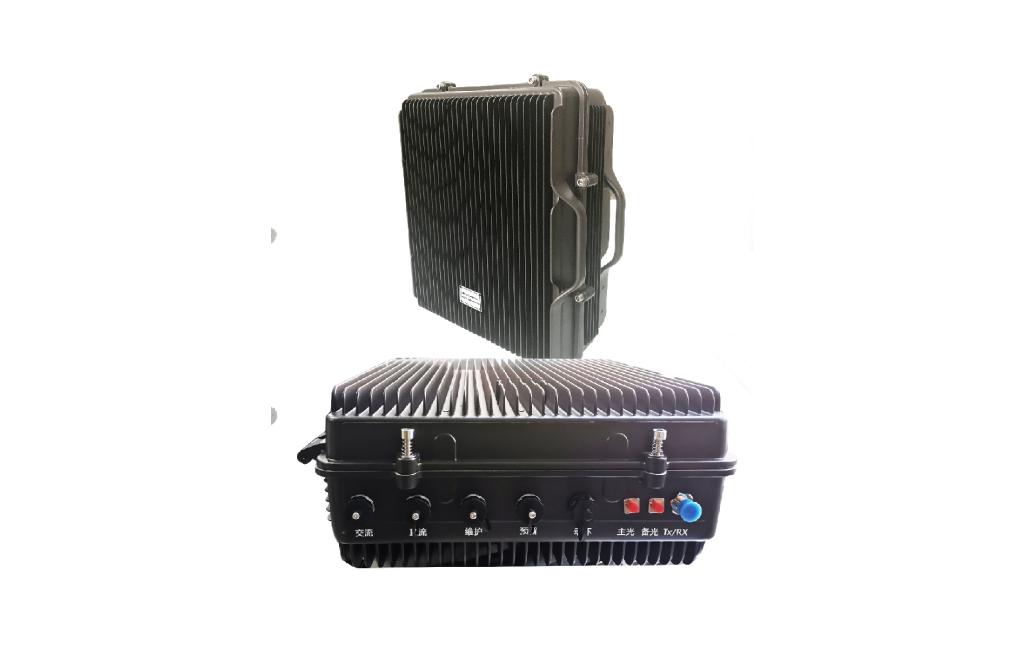
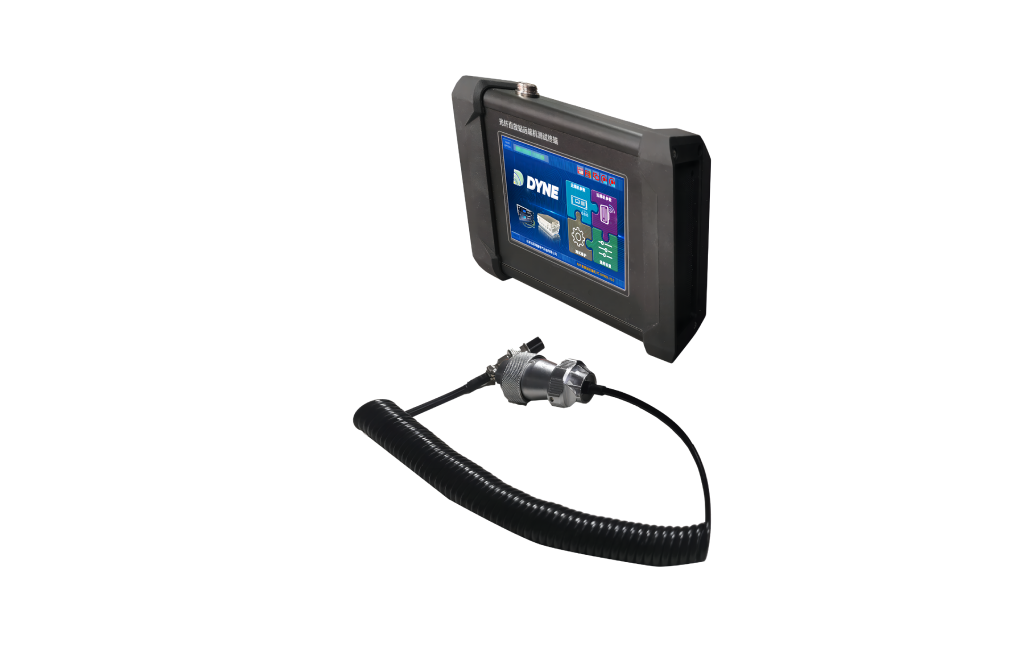

RC-TY800 Railway Fiber Optic Repeater
Product Features


Key Benefits

Dual Hot-Standby Redundancy
Critical components, including the power supply and power amplifier, adopt a dual hot-standby architecture, enhancing system redundancy and helping maintain continuous operation in the event of a component failure.

Independent Optical Link Architecture
The optical modules between the near-end and remote units adopt a one-to-one architecture.
Compared with conventional architectures in which one near-end optical module serves four remote units, the independent optical link design prevents a single near-end optical module failure from simultaneously affecting multiple remote units, helping reduce failure impact and improve overall system reliability.

Hot-Swappable Design
The RC-TY800 adopts a plug-in modular architecture that supports hot-swappable component replacement.
Modules can be replaced without powering down the equipment, helping maintain continuous radio coverage during maintenance and minimizing service interruption.
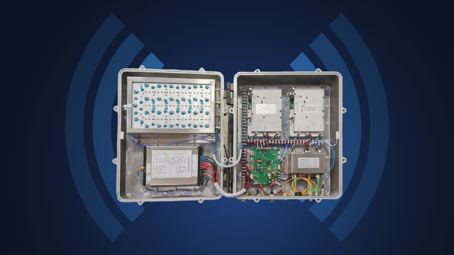
Dual Base Station Access
For systems requiring redundant coverage from two base stations, a single remote unit can simultaneously receive signals from two independent communication base stations, enhancing signal-source redundancy and overall system availability.
Dual Hot-Standby Redundancy
Critical components, including the power supply and power amplifier, adopt a dual hot-standby architecture, enhancing system redundancy and helping maintain continuous operation in the event of a component failure.
Independent Optical Link Architecture
The optical modules between the near-end and remote units adopt a one-to-one architecture.
Compared with conventional architectures in which one near-end optical module serves four remote units, the independent optical link design prevents a single near-end optical module failure from simultaneously affecting multiple remote units, helping reduce failure impact and improve overall system reliability.
Hot-Swappable Design
The RC-TY800 adopts a plug-in modular architecture that supports hot-swappable component replacement.
Modules can be replaced without powering down the equipment, helping maintain continuous radio coverage during maintenance and minimizing service interruption.
Dual Base Station Access
For systems requiring redundant coverage from two base stations, a single remote unit can simultaneously receive signals from two independent communication base stations, enhancing signal-source redundancy and overall system availability.


Industry Applications
Oil and Petrochemical Industry
The petroleum and petrochemical industry is characterized by high temperatures, high pressures, and flammable and explosive environments, where comprehensive wireless signal coverage is often difficult to achieve. With extensive expertise in the industry, Dynercomm has developed and standardized a complete portfolio of hardware, software, and integrated solutions tailored to diverse production scenarios, including digital trunked radio system base stations and production dispatch management platforms. Over the years, Dynercomm has accumulated extensive experience and a strong track record of successful projects.
了解更多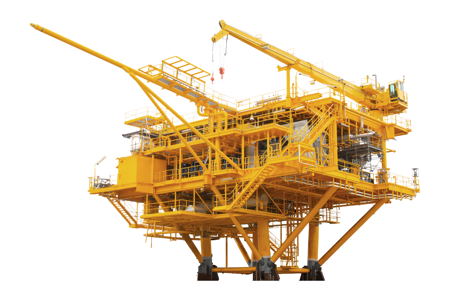

Industry Applications
Manufacturing Industry
Digital trunked radio communication and dispatch systems are essential for manufacturing enterprises. Efficient, customized, scenario-specific solutions, together with robust emergency response and safety mechanisms, help manufacturers transform their production models and improve operational efficiency. Communication devices featuring advanced noise cancellation and crystal-clear audio are also indispensable in demanding manufacturing environments. Our communication systems and products have delivered proven results across a wide range of manufacturing enterprises.
了解更多

Industry Applications
Mining Industry
Mining wireless radio communication systems consist of two coverage components: surface and underground. The surface base station serves as the functional core of the system, while leaky feeder cables are used as the transmission medium for underground signals, ensuring reliable wireless coverage throughout the mine.
Dynercomm’s “leaky feeder cable + repeater” architecture has been widely deployed in railway and highway tunnels for many years, offering mature, reliable technology.
了解更多

Industry Applications
Transportation and Logistics
Wireless radio communication systems are essential for ensuring on-time operations, preventing accidents, increasing transport capacity, reducing energy consumption, and supporting emergency rescue and incident response. Dynercomm’s radio communication system consists of radio terminals, control equipment, interconnection equipment, and ancillary devices. It is primarily used by dispatchers, station and yard duty personnel, train drivers, and on-site operating personnel for operational command, coordination, and routine communications.
了解更多

Industry Applications
Hospitality & Entertainment
For the hospitality and entertainment industry, a digital wireless communication system featuring extensive signal coverage, stable and reliable performance, and crystal-clear audio not only improves management and service efficiency but also enables a high-quality guest experience. Establishing an efficient and reliable management and dispatch environment is essential to ensuring dependable wireless communications.
了解更多

Industry Applications
New Energy
Dynercomm’s digital trunked radio system provides the new energy industry with a dual safeguard for efficient communication and safe operations and maintenance, offering energy and chemical enterprises a well-suited solution for improving production efficiency and reducing safety risks. Dynercomm’s products not only help create a safer working environment but also meet the communication needs of different project departments, routine production and operational dispatch, and emergency response in unexpected situations.
了解更多

Technical Specifications
| General Specifications | |||
|---|---|---|---|
| Parameter | Specification | ||
| Uplink | Downlink | ||
| Operating Frequency Band | 450 M | 458±1 MHz | 468±1 MHz /458M±1 MHz |
| 400 M | I: 403.7 ± 0.5 MHz | I: 413.7±0.5 MHz | |
| II: 413.1±0.4 MHz | II: 423.1±0.4 MHz | ||
| Maximum Output Power (dBm) | Uplink: ≥ −10 dBm Tolerance: ±2 dB under normal-temperature conditions; ±2.5 dB under extreme conditions. | Downlink: 37 dBm Tolerance: ±2 dB under normal-temperature conditions; ±2.5 dB under extreme conditions. |
|
| Maximum Gain & Tolerance (dB) | 50±2 | 50±2 | |
| Gain Adjustment Range (dB) | ≥30 | ≥30 | |
| Gain Adjustment Step (dB) | ≤1 | ≤1 | |
| Gain Adjustment Error (dB) | ≤±1.5 | ≤±1.5 | |
| Automatic Level Control (ALC) (dB) | When the repeater is operating at maximum gain and maximum output power, if the input signal level increases by up to 10 dB, the output power shall remain within ±2 dB of the maximum output power. If the input signal level increases by more than 10 dB, the output power shall remain within ±2 dB of the maximum output power or the output shall be disabled. |
||
| Maximum Allowable Input Level (dBm) | Remote Unit Input Port: ≥ −10 dBm without damage to the repeater; Near-End Unit Input Port: ≥ 10 dBm without damage to the repeater | ||
| In-Band Ripple (dB) | p-p≤2 | p-p≤2 | |
| Noise Figure (dB) | ≤5 | ||
| Minimum Squelch Threshold Level (dBm) | ≤ −90 dBm (450 MHz) | ||
| Input / Output VSWR | ≤1.4 | ||
| Spurious Emissions (dBm) | In-Band | 9 kHz-1GHz≤-36 | |
| Out-of-Band | 1 GHz-12.75GHz≤-30 | ||
| Intermodulation (dBc) | ≤-36 | ||
| Transmission Delay (μs) | ≤7 | ||
| Passband Characteristics (MHz) | −3 dB Bandwidth | >f0±1 | |
| −40 dB Bandwidth | <f0±5 | ||
| Allowable Optical Link Loss (dB) | ≥7 | ||
| Near-End Unit Power Consumption (W) | ≤100 | ||
| Remote Unit Power Consumption (W) | ≤200 | ||
We aim to provide our customers with…
Comprehensive Professional Communication & Security Solutions
- Comprehensive Project Requirements Assessment
- Practical and Feasible Project Recommendations
- Accurate Solution Quotation
"*" indicates required fields